Become a member of our Forum, and gain access to a lot more information!
Become a member of our Forum, and gain access to a lot more information!
|
HI Everyone, I have not been successful in conditioning the magnets. More than three years with no successful result. It has been six months since my last Update. I believe I have built the Conditioning Circuit so close to what was in the video that I should have seen some results. The video with Tom Bearden, John Bedini and Floyd Sweet showed what I believe to be the same conditioning fields, also using supporting information from John Searl's Conditioning. I believe conditioning of the Magnetic Field can be achieved but many thousands of Amps would be needed to achieve this and its very unlikely Floyd had a secret setup in his house with huge power supplies to do this. If so it certainly was not in the video which is what I have based my project on to date. My months of tunning to the circuit and more research have led me to another path of investigation. I keep thinking of the term "Space Quanta Modulator" This means to me that the SQM/VTA is Modulating the Space Quanta, Quanta being the Magnetic Flux. So is it possible that the Machine itself (SQM/VTA) IS the Modulator of the Space Quanta?
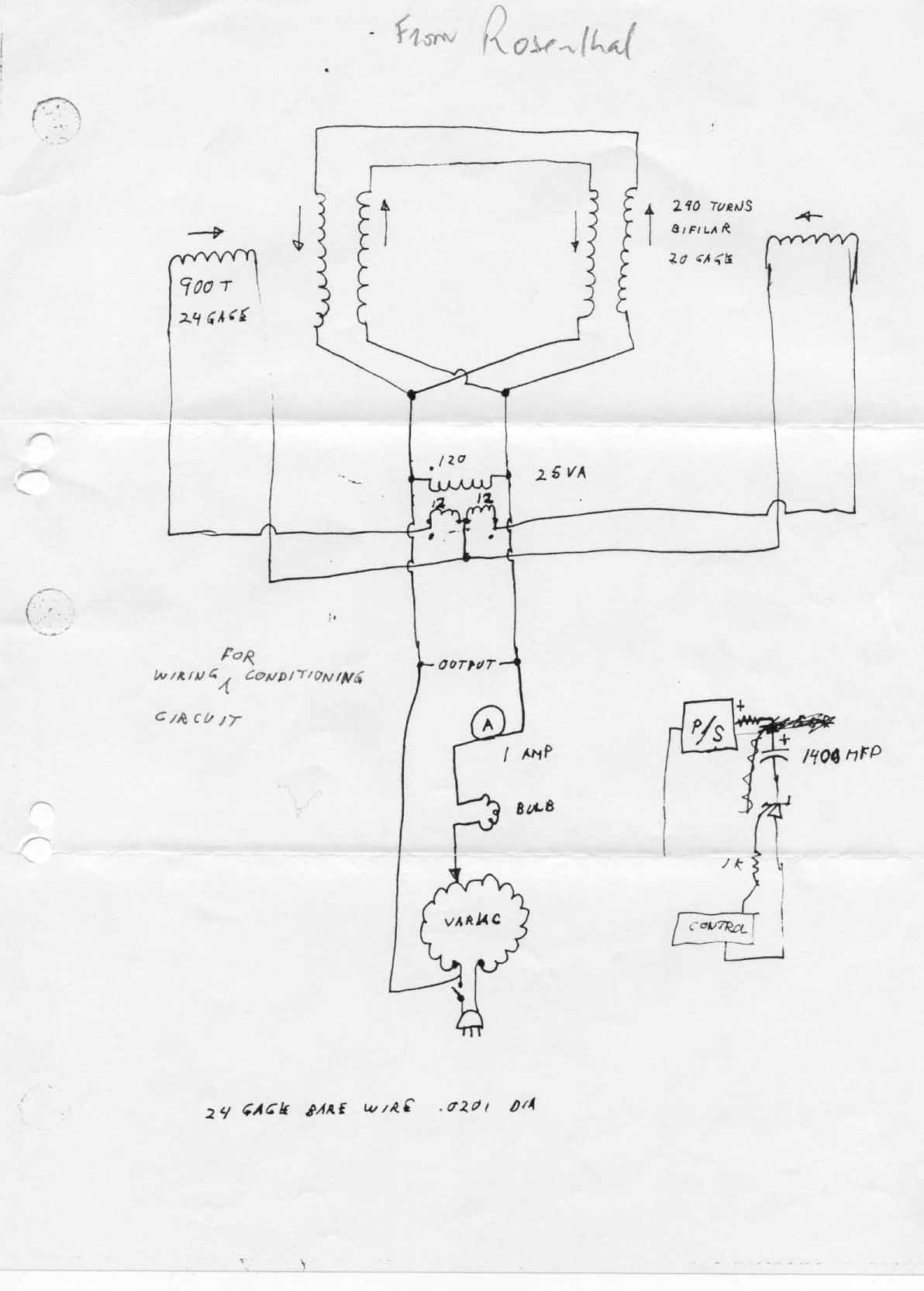
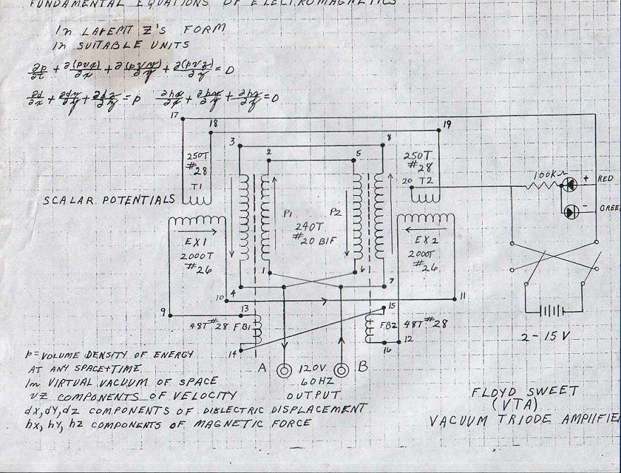
A lot of people may not agree with me on this but I think it is necessary to investigate this possibility. There is a lot of supporting evidence that when NOT in operation that the SQM/VTA had NO moving flux from the Magnets. This means Conditioning of the Magnets IS the Starting of the SQM/VTA and there is no requirement to have Moving Magnetic Flux until the SQM/VTA is started. There is a strong possibility that the Coils themselves actually put the Magnets Flux into Movement in an oscillatory method. Now you may say Oh Come On... Well there is evidence through History for such a thing to happen. Now the best I have seen and was put on to by a kind Gentleman is Daniel McFarland Cook's Electro Magnetic Battery. I will Bullet Point some of the better Evidence. 1: First and MOST important is the above two schematics. The similarities are not just a coincidence. I have been told by a person that worked with Floyd that the second schematic does appear to be Floyd Sweet SQM/VTA Schematic and this is a valid document. We know that Floyd had at least three variations of the SQM/VTA. It has been said that Floyd changed things all the time. I guess as improvements were made things had to change. Some pictures below of the models I have been able to find:
2: From the book "Energy From The Vacuum" by Tom Bearden. Please help support Mr Bearden by buying his book. Information provided by Walt Rosenthal:
"Figure 6-12 shows the
set-up for the tests, with the unit and loads as well as some of the instruments
used. Figure 6-13 shows the closed-loop VTA powering itself and its loads, after
being initially set into operation with outside input power by the operator, and
then adroitly switched into self powering by switching the input from external to
internal at an output
Figure 6-12 The 2-magnet, 2 coil VTA, loads, and instruments for its historic self-powering operational tests on May 1,1990. Also information from John Bedini stated that " I also knew the process of his box, there were no magnetic bubbles, no magic magnets, and no special conditioners that will make the box work, but there was a special process of which Sweet's own son did not know, he was an EE and could not understand how it worked. I know because I was there helping him at night."3: Daniel McFarland Cook's Electro-Magnetic Battery: http://my.voyager.net/~jrrandall/CookCoil.htm (This is an excellent piece of information). 4: From records of T Henry Moray: "
" 5: The Great Nikola Tesla stated that "A Coil can be used to temporally store Energy". Anyone that has been following John Bedini and others working in the Capture of the Radiant Energy can verify this. The fact that a Magnet was used in most of the devices in the past that have any correlation to COP =>1 machines is something to think about. We need to generate a Back EMF with Amperage to keep the SQM/VTA in operation. To start the Device a power input is needed. This is used to separate the lines of Flux between the Magnets in the Starting coil. To visualise this the picture below is provided. Top and Bottom Magnets are the magnets in the SQM/VTA. The Middle Magnet is the starting Coil and Power coils. While this coil is on there is a repulsive mode.
Now the Flux collapses back in on itself and lines of Flux join together in attraction mode. Generating Current on the collapse. Like in the schematics there are two Power Coils and they Oscillate between each other. One is in Repulsive mode while the other is in attractive mode. Like Tom Bearden says: "HIGHLY OUT OF EQUILIBRIUM". The Magnets in putting Energy into the system.
So, we have a possibility of having a self generating Oscillation if the coils are setup right in the SQM/VTA. Like for example in the above schematics. Now the funny part. I think it is very possible that a capacitive discharge may be needed to set this in operation because the Current/Amperage on the Magnetic Flux Collapse is needed to keep this operation going. For efficiency and to aid in operation, reducing Lenz's is something we always want to do, so insulated soft iron/Steel wire can be used as the core for these coils. No core is needed in the Excitation coils, as far as I can tell, that sit at right angles. Now as yet this is something I have not been able to make work but it is sound in its theory and only makes sense given the supporting evidence. So build it try it and let me know your results. Well more coming soon as always. |